|
|
|
BY1 Surge
Protective Device
|
|
|
|
|
|
|
|
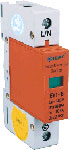
BY1 1P
|
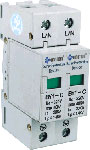
BY1 2P
|
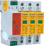
BY1 3P
|
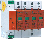
BY1 4P
|
|
|
|
|
|
|
|
|
|
|
|
|
|
|
|
|
|
| 1.Introduction |
|
|
|
|
|
|
|
|
|
|
|
|
|
|
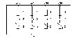
| Indicator\Model
|
BY1-D
|
BY1-D
|
BY1-D/2
|
BY1-D/4
|
BY1-C/2
|
BY1-C/4
|
BY1-B/4
|
|
Rated voltage un (V~)
|
75
|
110
|
220
|
380
|
220
|
380
|
380
|
|
DC reference voltage un(~)
|
120
|
200
|
510
|
680
|
510
|
680
|
510
|
|
MAX. Continued running voltage
|
Uc~
|
75
|
130
|
320
|
420
|
320
|
420
|
510
|
|
Uc~
|
100
|
170
|
415
|
560
|
415
|
560
|
415
|
|
Voltage protector level
|
Is=1kA
|
0.24
|
0.39
|
0.9
|
1.2
|
0.9
|
1.2
|
1.0
|
|
Is=5kA
|
0.3
|
0.45
|
1.0
|
1.5
|
1.0
|
1.5
|
1.1
|
|
Is=10kA
|
0.35
|
0.5
|
1.2
|
1.7
|
1.2
|
1.7
|
1.3
|
|
Is=15kA
|
|
|
|
|
1.3
|
1.8
|
1.4
|
|
Is=20kA
|
|
|
|
|
1.4
|
1.9
|
|
|
Is=30kA
|
|
|
|
|
|
|
1.9
|
|
|
Is=40kA
|
|
|
|
|
1.9
|
2.6
|
|
|
|
Is=60kA
|
|
|
|
|
|
|
2.6
|
|
Nominal discharging currrent
Isn(8/20us) 20 times(KA)
|
5
|
20
|
30
|
|
Maximum discharging currrent
Isn(8/20us) 20 times(KA)
|
10
|
40
|
60
|
|
Respond time
|
<25
|
|
Energy resist (2000us)(A)
|
200
|
|
Ambient temperature
|
-40℃~+80℃
|
|
Color:
|
Mould
|
Grey
|
Orange
|
|
Base
|
Grey
|
|
Material
|
Reinforced fire-retardant
nylon
|
|
Connecting Specification
|
Phase wire, earth wire
|
2.5~35mm
|
|
Earth wire
|
4~35mm
|
|
Indicating wire
|
1.5mm
|
|
|
|
| When the power system
suffered thunder or other reasons, it produces high frequency pules voltage.
The electrical equipment will be damaged. Especially with the large use
of computer and microelectronic facilities, people have concerned the over
voltage protector of low voltage power system. BY1 surge voltage protector
is the best production in protection. |
|
|
|
|
|
|
|
| 2.Operaring tenet |
|
|
|
|
|
|
|
|
|
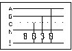
| n three-phase four
lines system, three-phase lines and one zero line are connect protector
for the earth cable.(Fig 1). In normal situation, the surge voltage protector
is high resistance. When the power system or other reason appear the surge
over voltage, the protector will rapidly transmit, then it will lead the
voltage into earth and protect the electrical equipment, as the surge voltage
through the protector and after disappear the surge voltage protector recover
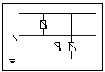
to high resistance and it will not influence the normal run. Single phase
220V electrical tenet (fig.2) Surge voltage protector tenet(fig.3) |
|
|
|
|
|
|
|
| 3.Features |
|
|
|
|
|
|
|
|
|
|
A)Mould--no cut off
current it can replace protector unit.
B)Large current--the maximum current 40KA(8/20us)
C)High rapid--operating responses time less 25ns
D)Display form--windows colors indicating the
protector working state, Green(normal) Red (trouble).
E)Appendant function:
I. Acoustic optic alarm
II. Trouble tele-control contact
III. Thunder counter
IV. Waterproof case |
|
|
|
|
|
|
|
|
|
|
|
|
|
|
5. Appearance and
Mounting dimension: Protective device adopts 35mm DIN rail type mounting
appearance dimension see attachment |
|
|
|
|
|
|
|
|
|
|
|
|
|
| 6.
Warning and counter specification: Warning and counter(alarm)is consist
of acoustic optics alarm and thunder counter, its function as follows: |
|
|
|
|
|
A).
AC 220V power supply for alarm, as the protector normal works that the pilot
lamp is green, NO contact is closed, NC contact is cut off. |
|
|
|
|
|
|
|
B).
Acoustic optic alarm function: After the failure of protector mould, the
buzzer, at the same time the green light change into red light. If you
push the stop alarm button, the buzzer will pause (but red light continued),
after 24 hours, if the trouble is not cleared,the buzzer call again.
|
|
|
|
|
|
C). Telecontrol
function:
The alarm is buzzing and it also can drop out close and cut off contact,
for distance monitor. |
|
|
|
|
|
|
|
|
|
|
E).
Self-inspection, zero function:
Push stop button making current it can self inspection and finish the numerals
pipe operating. |
| D).
Counter function: The alarm can display the protector’sworktime, after push
the stop button the numerals pipe appears the data is work time. |
|
|
|
|
|
|
|
|
|
|
|
|
|
|
|
|
°